소프트웨어 공학 관련 자료
Posted 2007. 9. 21. 16:34- Filed under : 카테고리 없음

February 2004
In ancient computing times, a wise system architect once said, "you can't manage an application you can't monitor." In many cases, documenting the design for a new application, let alone how it might be monitored, is typically beyond the scope of the project. This article describes a reusable mechanism for capturing application-bound, performance statistics for highly distributed J2EE applications.
Applications essentially need to be engineered to support established service levels (i.e. Service Level Agreements). In some cases, SLA might be very granular, such as, stating the elapsed time expected to persist data related to a person. The architecture depicted in Figure 1 was implemented to handle an Internet order entry, including a self-service feature to allow a customer to update his own profile.
Figure 1. Distributed J2EE Architecture
Because of expectations of high order volumes, the application was engineered to provide distributed EJB transactions, which can be pooled and clustered for high availability and scalability. Highly distributed applications not only need to be engineered from a distributed object standpoint, but from a load balancing and clustering perspective, too. The architecture does not reflect load balancing and clustering implementation details.
This document describes a basic methodology for performance testing the distributed architecture. Essentially, the document describes the design and edits required to collect basic instrumentation/timing estimates for a distributed J2EE application.
The J2EE application relies on five tiers: a Web, EJB, EAI (Enterprise Application Integration), ERP (Enterprise Resource Planning) and DBMS tier. An Internet client makes an HTTP request to the Web tier and forwards the request over RMI/IIOP to the EJB tier. The EJB tier communicates with the SeeBeyond EAI tier using a SeeBeyond MUX e*Way . The EAI tier communicates with the Peoplesoft CRM (Customer Relationship Management) application within the ERP tier using a Peoplesoft adapter. Finally, The CRM application integrates with an Oracle DBMS over SQL*net.
A key part of any distributed environment is the time server. Within the methodology, instrumentation metrics are collected on the server where the code is executed, so it is important that all machines within the distributed J2EE architecture are time synchronized. Within the IBM AIX UNIX environment, the xntpd daemon sets the internal clock time on a machine. The service is used to synchronize time services with an external machine using the Network Time Protocol (NTP). Typically, there is a time server, which does not necessarily need to be another AIX or UNIX machine, within an organization's network that all machines synchronize with on startup. (In reality, machines with xntpd configured synchronize constantly, not just on startup.)
Alternatively, a machine can synchronize with an external time server on the Internet. The xntpd daemon defaults to off, so time settings, such as the IP address of the time server to synchronize with, needs to be configured within an ntp.conf file. Since instrumentation metrics are collected at the second or even millisecond levels, discrepancies between machines can lead to spurious performance statistics.
The proposed J2EE architecture relies on a number of well-known design patterns, such as the Business Delegate (a.k.a. Proxy), Data Access Object, Model-View-Controller, Session Facade and Transfer Object (a.k.a. Value Object). A transfer object is a serializable class that groups related attributes, forming a composite value. In the architecture, the Transfer or Value Object is used as the return type of a remote business method, such as an Enterprise JavaBean. Fetching multiple attributes through the value or transfer object in one server roundtrip decreases network traffic and minimizes latency and server resource usage.
Figure 2 depicts the PersonValueObject, which implements IPersonValueObject and Serializable interfaces. The PersonWorkerBean uses a PersonValueObject for containing person and instrumentation attributes. Instrumentation attributes are long values, which contain a timestamp from calling System.currentTimeMillis(). The PersonValueObject also includes accessor methods for all attributes.
Figure 2. UML Class Diagram Value Object Specification (a.k.a Transfer Object)
While it is good OO practice to provide accessor methods instead of allowing direct manipulation of instance variables, it also increases overhead by imposing an additional method call. You want accessors to hide the implementation of get and set, and to allow subclasses to change the synchronization of a get or set, but there will be an overhead cost. Value objects can be sub-classed or they may have associations with other Value objects. For example, if requirements dictated that all Value objects in the application needed to be performance tested, refactoring instrumentation operations within a "FrameworkValueObject" would strongly be recommended. In this alternative specification to Figure 2, the PersonValueObject would extend the FrameworkValueObject and implement the IPersonValueObject interface; the IPersonValueObject interface would extend the IFrameworkValueObject interface. However, the operations listed in the IPersonValueObject would be the same as depicted in Figure 2 for either specification. The advantage to using this model is that all value objects would extend the FrameworkValueObject and therefore have instrumentation behavior; however, this is a complex relationship, and while correct from a UML (Unified Modeling Language) perspective, in and of itself would exert a performance cost to the application.
For value objects that have a direct association with other value objects, those relationships are implemented as class instance variables. UML recommends that for value objects that have an aggregation or composition association with other value objects, those relationships should be implemented as a Collection. A Collection is the root interface in the Java Collection hierarchy. A Collection represents a group of objects, known as its elements. This interface is typically used to pass collections around and manipulate them where maximum generality is desired. For example, a PersonValueObject contains one to many AddressValueObjects or a Collection of AddressValueObjects. However, this relationship is not included in the diagram, because it is not related to capturing timing estimates, but it is important to "real world" applications.
The objective of the methodology for this project was:
Once the value object was wired for collecting instrumentation/timing, instrumentation edits were required in the J2EE and SeeBeyond application code. This required identifying the objects that would set timing estimates into the value object for the tier, and which object would be responsible for getting the estimates and writing them to a log file. The number of places in the code that timing metrics were collected was, in a way, an arbitrary decision. It was determined that the following objects needed to be reworked:
The input for testing the application was generated using Mercury Interactive's LoadRunner via an HTML browser; this discussion, however, is out of scope for this report. Internet/network timing estimates, that is, download time from the HTTP server to the browser, are not collected through the value object; intranet download timing estimates must be imputed by estimating elapsed overall response time through LoadRunner minus PersonValueObject timing estimates collected in the framework_log4j.log.
The target of the log4j log output can be a file, an OutputStream, a java.io.Writer, a remote log4j server, a remote Unix Syslog daemon, or even an NT event logger, among many others. The performance of the log4j package is also quite good. On an AMD Duron clocked at 800Mhz running JDK 1.3.1, it costs about 5 nanoseconds to determine if a logging statement should be logged or not. Actual logging is also quite fast, ranging from 21 microseconds using the basic configuration.
It is important to point out that the purpose of the methodology is not memory and CPU application profiling as would be performed by tools such as JProbe from Quest Software or Optimizeit form Borland. The only tools that are engineered for distributed performance monitoring similar to the methology discussed here are PathWAI Dashboard from Candle Corp. and Introscope from Wily Technology.
Figure 3. UML Sequence Diagram - Create a PersonValueObject
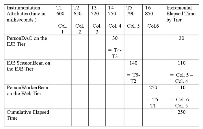
A successful execution of the application from the Step 1 createPerson on the PersonWorkerBean to Step 23, writing the timing data to a Log4j log file would result in a single row that can be parsed into the following matrix. Timing estimates are collected in milliseconds. The table below is used to depict the elapsed time for processes within the application tiers, which is somewhat an arbitrary decision based on requirements. In effect, various permutations and combinations of processing times can be estimated, as long as the analyst/programmer has a solid understanding of the context of the timestamp captured. For example, 250 represents the total elapsed time marshaling the PersonValueObject from the Web tier through the entire application, whereas, the Incremental Elapsed Time Column is an imputed estimate for processing within tiers.
Step 1: Implement instrumentation code edits for the IPersonValueObject Interface for the PersonValueObject Class (see Figure 2).
Step 2: Implement instrumentation code edits for the PersonValueObject Class (see Figure 2).
Step 3: Instrumentation code edits for the log4j.xml that sets priority level for application logging to the framework_log4j.log file. log4j relies on a configuration file for runtime settings. It also provides an ability to dynamically set the log levels (i.e. DEBUG, INFO, WARN, etc.).
<?xml version="1.0" encoding="UTF-8"?>
<!DOCTYPE log4j:configuration SYSTEM "log4j.dtd">

<log4j:configuration
debug="true">
   <appender name="TEMP"
       class="org.apache.log4j.FileAppender">
      <param name="File" value="framework_log4j.log"/>
      <layout class="org.apache.log4j.PatternLayout">
        <param name="ConversionPattern" value="%d - %m%n"/>
      </layout>
   </appender>
   <category name="proofofconcept">
      <priority value="info"
      <appender-ref ref="TEMP"/>
   </category>
</log4j:configuration>
Step 4: Implement instrumentation code edits for the PersonWorkerBean (see Figure 3). The PersonWorkerBean logs the timestamps to the framework_log4j.log file by invoking a log4j.info method on a static reference to the Log4j Logger class. There are really two key classes: the PropertyConfigurator and Logger. The PropertyConfigurator.configure method is used to pass the location of the configuration file. The Logger is used to set the logging messages, the logging level and to identify which classes in the application you want to log errors for. The recommended pattern for extending the Logger class within Log4j is wrapping or creating a reference. It is strongly discouraged that users subclass either the Logger classes. Log4j provides an ability to (dynamically) set the log levels (i.e. DEBUG, INFO, WARN, etc.) or provide the level through a configuration file. By setting the level to "info", all messages of "info" and above will be written to the log file. Provided that the application does not throw any exceptions, there should be only one "info" message written to the file, which includes timing estimates for all middleware tiers.
Step 5: Implement instrumentation code edits for the PersonServiceSessionBean (see Figure 3). The PersonSessionBean create method receives a serialized copy of the PersonValueObject, sets the estimate into the PersonValueObject and calls the createPerson on the PersonDAO. In the model, the DAO is used to get a connection to the SeeBeyond EAI application server, and the PersonValueObject is not directly persisted into a DBMS. The point is, that in most J2EE applications, the Data Access Object pattern is used to specify how to persist data into DBMS.
Step 6: Implement instrumentation code edits for the PersonDAO class (see Figure 3). The createPerson method on the PersonDAO sends the PersonValueObject to the SeeBeyond application server using a MUX e*Way, a synchronous protocol. For this implementation, the PersonValueObject attributes where sent as a test message, because the SeeBeyond application server only supported text messages. The returning message from SeeBeyond, because it represented a string, not a PersonValueObject, needed to be parsed using a StringTokenizer. This edit for instrumenation code assumes that there are 3 tokens in the order in the format "Id^timeStamp1^timeStamp2." The Id is generated by SeeBeyond and represents the primary key for the PersonValueObject created.
The SeeBeyond application server provided timestamps for integration with the Peoplesoft CRM. SeeBeyond also returned the generated primary key, which would be required for persisting associated value objects, such as Address value objects. This is not modeled in the UML sequence diagram, because the central theme is how to collect timing estimates within disparate computing tiers.
protected IPersonValueObject createValueObject(
    String rs )
    {
        IPersonValueObject valueObject = null;
        try
        {
            valueObject = getPersonValueObject();
            if ( valueObject == null )    // create one
            {
                valueObject = new PersonValueObject();
            }
               StringTokenizer st =
                  new StringTokenizer(rs, "^");
               PersonPrimaryKey pk =
                  new PersonPrimaryKey(st.nextToken());
               valueObject.setPrimaryKey( pk);
               valueObject.setT3( Long.parseLong(st.nextToken()));
               valueObject.setT4( Long.parseLong(st.nextToken()));
                      }
        catch ( Exception exc )
        {
            printMessage("PersonDAO:createValueObject()-" +
                         exc );
        }

        return( valueObject );
    }
Ideally, the best design would allow for a ValueObject to be passed to all middleware tiers. SeeBeyond on the EAI tier actually has asynchronous support using JMS (Java Messaging Service) text messages, but not for JMS ObjectMessage type messages. Most implementers would prefer ObjectMessage type messages. For example, with an ObjectMessage type using JMS, the PersonValueObject would not have been parsed into a String object, but could have been sent directly to SeeBeyond . ObjectMessages - messages containing a serialized Java object - make it clear to programmers which data type and attribute they are receiving and sending. With support for JMS ObjectMessages, the PersonEAI object depicted in Figure 4 could have been implemented in SeeBeyond, which could have marshaled directly the PersonValueObject. For distributed object programmers, this is what it is all about -- transferring objects around the network.
Figure 4. View of participating classes for UML Sequence Diagram - Create a PersonValueObject
Frank is a Lead Architect specializing in J2EE application design and implementation of enterprise-wide applications. He can be reached at frank_teti@hotmail.com.
When SOAP Just Won't Do, Network Computing, 11/03
http://www.networkcomputing.com/showitem.jhtml?docid=1424ws1
Design for EJB Message-Driven Beans with UML Use Cases, Enterprise Architect, Winter 2003
http://www.ftponline.com/ea/magazine/winter/columns/modeling/
The new world of clustering, Application Development Trends, 12/01
http://www.adtmag.com/article.asp?id=5752
Boosting Java Performance, Application Development Trends, 12/00
http://www.adtmag.com/article.asp?id=2667
참고 ^^ ============== !!
http://www.theserverside.com/tt/knowledgecenter/knowledgecenter.tss?l=ContinuousPerformance
http://www.theserverside.com/tt/knowledgecenter/knowledgecenter.tss?l=BroemmerPerformance
http://www.theserverside.com/tt/knowledgecenter/knowledgecenter.tss?l=DistCompute
http://www.theserverside.com/tt/knowledgecenter/knowledgecenter.tss?l=TestingConcurrent
http://www.sei.cmu.edu/str/descriptions/cbsd.html
http://www.cebase.org/www/frames.html?/www/researchActivities/COTS/integrationmodels.html
http://www.ncca.navy.mil/services/software/cots.pdf
http://www.computer.org/portal/cms_docs_software/software/content/value.pdf
http://tharkun0.ucsd.edu/ResearchCentral/download.jsp?id=138
http://www.stargroup.uwaterloo.ca/~ltahvild/courses/ECE750-11-S05/CBSS-Lecture10.pdf
http://www.eetkorea.com/ARTICLES/2004FEB/2004FEB02_ICD_EDA_TA.PDF?SOURCES=DOWNLOAD
http://www.omg.org/news/meetings/workshops/MDA-SOA-WS_Manual/02-3_Cummins.pdf
http://aswec07.cs.latrobe.edu.au/14.pdf
http://sunset.usc.edu/GSAW/gsaw2006/s4/hohwald.pdf
http://csdl2.computer.org/persagen/DLAbsToc.jsp?resourcePath=/dl/proceedings/&toc=comp/proceedings/iccbss/2007/2785/00/2785toc.xml&DOI=10.1109/ICCBSS.2007.46
http://colab.cim3.net/file/work/SOACoP/2006_05_2324/CCasanave205222006.ppt
http://www.army.mil/armybtkc/test/sa/soa.htm
오래된 이야기..거버넌스가 힘들다. Cots에 대한 Integration은...
현재 몸으로 겪고 있음.
몇개월째..T.T
※ 아키텍처는 소프트웨어 아키텍처를 뜻합니다.
최근 아키텍처에 대한 품질 평가를 하면서 몇몇 새로운 것들을 느끼고 있다.
엔지니어들이 느끼는 아키텍처란게 무얼까? 6년전에 만든 아키텍처 문서를 보면서 품질팀에서 아키텍처에 대한 품질을 검사 할 수 없음을 다시 한번 느끼고 있다.
아키텍트는 아키텍처의 품질 담당자이며 이로 인해 아키텍트가 책임을 지는 일은 상당히 크다라고 할 수 있다.
어떤 품질에 포커스를 하느냐에 따라 QA( Quality Attribute ) 의 느낌감도 (?) 는 상당히 다르다는 것이다.
어떤 이는 ATAM을 너무나 쉽게 거론하기도 한다.
최근 모 회사의 아키텍처 문서를 평가하면서 많은 것들을 느꼈는데… 최근에 제품위주(COTS) 의 아키텍처가 아키텍트들의 머리에 또 다른 사고를 만든다는 것도 알았다.
그러기 위해서는 COTS를 위한 아키텍처가 필요하며 이에 맞는 적절한 평가가 필요하다고 생각된다. 페이지수가 많거나 학구적이라고 해서 아키텍처 문서라고 하기엔 너무나 고리타분하고…. 외국서적에 나온 듯이 그대로 배낀 패턴이나 스타일로 뒤덮힌 아키텍처 문서도 난무하며… 정말 그런 문서들이 아키텍처 문서인지는 잘 모르겠다.
개발자입장에서 디자인패턴을 써놓는다고 해서 아키텍처라는 말을 붙이기엔 아키텍처라는 말이 너무나 광범위하고 어떤 면에서는 협소하다고 생각한다.
최근 몇 년간 SEI 에서 나온 시리즈 물을 몇 번 정독하고…
포사1.2를 쪼개고…
각종 Object문서를 봐도 봐도…
현장에서의 아키텍처문서엔 어떠한 면에선 현실적인 내용이 들어가긴 힘들다는 것이다.
그저 현학적인 문서들….. 책을 아무리 많이 봐도 익혀지지 않는 것들이 많은 것은
책의 장수만을 세거나 아니면 너무나 현학적인 책을 봐서 아닐까….. 반성해야 한다.
아키텍처 문서에는 이러한 것들이 들어있으면 좀더 많은 이해관계자들이 공감하기 좋을 것이다.
하도 많아서 기술하기 힘들지만…. 대략 저러하다.
또다른 뷰에서 본다면 아키텍처 정의를 위한 문서들은 어려워서는 안되며 가장 쉬운 것으로 추상화되어 표현되어야 한다는거….
http://www.osoa.org/display/Main/Relationship+between+SCA+and+BPEL
Sometimes, when talking about composite service-based applications, people get confused about the roles of SCA and of BPEL and consider that these two technologies are in conflict or that they are trying to perform the same roles. This isn't the case - far from being rivals, SCA and BPEL are firm friends and are complementary parts of a business solution, each with its own role to play.
However, the similarities between SCA and BPEL show why there is the possibility for confusion. First, both BPEL and SCA are described in terms of a formal language that is based on XML. Secondly, both languages may be used to describe a business service that is implemented by composing together other business services and both can describe inbound and outbound service interactions types by WSDL port types. There the similarities end. The important difference between SCA and BPEL is that SCA is all about describing the structure of the application while BPEL describes business logic involving the sequencing of operations in a business process.
Putting this in another way, SCA is concerned with what components exist in the business application, what services those components offer, what service references those components depend on, how the components are connected together, what endpoint addresses and communication methods are used for the connections, what policies are applied to components and to the connections between them. BPEL is concerned with business logic and the sequences of operations which are performed to execute an individual business process. BPEL processes provide and consume other services through partnerLinks, but these are abstract interfaces that must be connected to actual endpoints and communication methods through configuration.
So, SCA describes the structure of a business solution in terms of business components and their connections, but the sequence in which particular services are invoked is determined by the business logic of the implementation used for each component. It is a good combination when the components are implemented as BPEL processes within an overall SCA assembly, since then it is possible to get a combined view of structure and sequence. Of course, SCA does not force this as a requirement and components may be implemented in any supported programming language, such as Java or C++. In this case, sequence decisions are made in the implementation language of the component and it may be harder to work out the sequences involved.
So, BPEL and SCA are the firmest of friends and work well together when building business solutions as sets of services. The following sections provide some details and some examples as to how this works in practice.

SCA is useful for describing the structure of composite service applications. To get a better sense of what this means, an example application is shown in the following diagram:
In this example, the Order Processing service is offered for use by customers, most likely as a Web service available over a general protocol such as SOAP over HTTP. This may have a set of operations such as "createOrder", "checkAvailability", "getOrderStatus" and so on.
The Order Processing service is implemented by the OrderProcessing Component. In turn, the OrderProcessing component makes use of services provided by other components, represented by the EventLog component, the AccountsComposite and the WarehouseComposite. The names of those components already indicate how they are implemented - EventLog is a simple implementation, for example a Java class, while AccountsComposite and WarehouseComposite are each a composite set of components which work together to provide the services used by the OrderProcessing component.
The OrderProcessing component does not need to know the structure of the AccountsComposite or the WarehouseComposite - but the assemblers and developers responsible for those parts of the solution certainly do!
So, SCA shows what components make up a particular business solution and it shows how they are connected together. SCA provides more information than this, if it is needed. For example, SCA knows what binding is used for each connection. The OrderProcessing component may, for example, connect to the PaymentService using an EJB binding, if the AccountsComposite is implemented as a Java EE application using EJBs. Meanwhile the OrderProcessing component might connect to the WarehouseService using a JMS binding using an underlying messaging infrastructure. SCA may also apply particular policies to these connections. For example, accounts information may be regarded as sensitive and so require that all operations on the PaymentService are encrypted. The same operations may also require authentication to ensure that only trusted users are invoking the operations. Meanwhile some of the operations on the WarehouseService, such as those involved in dispatching orders to the customer, must be performed transactionally and reliably, so that the OrderProcessing component can be assured that the order is dispatched once and once only.
What SCA does not do is in any way show the sequences of operations associated with the OrderProcessing service. So, the checking of the customer's account status, the checking of the inventory status of the order items, the calculation of the price of the order items, the billing of the customer, the request to dispatch the goods to the customer - all these operations (and more!) may be required to complete a "createOrder" operation, but their sequence is entirely determined by the code used as the implementation of the
현 프로젝트에서 적용중 -.0- 그러나 난관은 있다.
내가 생각하는 SOA모델이 가장 잘 일치하는 것은 IBM의 SOA모델...
이 이야기를 좀 적어보까 ^^
어디부터 시작을 해야 이게... 적히게 될려나....
정치부터 해야 하나 -.T